

- HOME >
- TECHNICAL >
- Article >
- Audio Technology >
- 音箱技术 >
- What’s The Delay? The Effects Of Weather Conditions On Sound


- Others
- 音箱技术
-
What’s The Delay? The Effects Of Weather Conditions On Sound
Summer is here, and a good many of us are out working those “mud and dust” shows, fairs and festivals.
We get to clean amplifier filters on a daily basis, put wedges into garbage bags to keep them dry, mix with visqueen draped over the console (also to keep it dry). And, we’ll have a shop vacuum at front of house as well as the monitor “beach.”
That said, the toughest aspect to deal with when doing shows in the great outdoors is the effects of atmospheric conditions on a system’s behavior. Temperature changes, as well as wind and humidity can wreak havoc on our carefully aimed and tuned rigs.
And the larger the venue, the greater the effect that these conditions will have on sound propagation. The effects are not preventable, but at least they’re (at least partly) predictable.
Morning, Noon & Night
Any time you’re doing sound outside, temperature gradients are an issue. In the morning, the ground retains the nighttime coolness longer than the surrounding air, resulting in a cool air layer near the ground with a warmer layer above it.
The velocity of sound increases slightly with higher temperatures. For example, at an elevation of 0 feet above sea level, at a temperature of 50 degrees (Fahrenheit), sound will travel 110.7 feet in 100 milliseconds (ms).
At 90 degrees F, it will travel 115.14 feet in the same 100 ms. This will force the wavefront angle of sound from loudspeakers to track slightly downward, bending toward the cold air layer.
In more extreme conditions, sound waves can actually bounce off the ground and skip over part of the audience before refracting downward again further on, causing dead spots in the system coverage.
In the evening the opposite happens. Because the ground is still warm while the air is cooling off, a layer of heat is trapped near the surface. Thus the wavefront angles upward, and can be refracted right over the top of the crowd. (Note also that the warm air layer generated by the crowd itself increases this tendency.)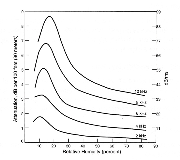
Excess loss with distance due to reltive humidity in the air. (Graphic courtesy of JBL Audio Engineering For Sound Reinfocement by John Eargle and Chris Foreman (click to enlarge)
Wind can produce similar effects. The speed of sound traveling with the wind will equal the speed of sound plus the wind speed; thus, when sound is firing into the wind, you must subtract the wind speed.
And since the wind speed in a boundary region like the ground is at or near zero, a wavefront heading into the wind will refract upward as the top part of the wave is slowed slightly by the headwind.
With the wind behind sound - pushing it - the wave will bend downward. It’s not the wind itself that causes problems, but the velocity variations with altitude. The effects of a crosswind can be analyzed with a little simple trigonometry. (Is there really any such thing?)
Let’s look at an example. Start with the fact that the nominal speed of sound is 770 miles per hour (mph). Then, let’s say that a crosswind is blowing at 90 degrees to the direction of the sound system propagation at a rate of 40 mph.
We can use those speeds as distances on the legs of a right triangle and determine the angle of deflection. In this example it’s about six degrees.
However, this can be a little deceiving. Because the typical cluster may have a horizontal dispersion of 120 degrees or more, part of the wavefront is moving perpendicular to the wind, but other parts are quartering into the wind or away from the wind.
This causes their behavior to be affected as though the wind were pushing the sound as noted above. Very complex!
More & Less
Humidity is another factor that can produce large changes in sound system propagation but this time in the frequency domain.
Although it can seem counter-intuitive, lower humidity equals more attenuation and higher humidity equals less.
Humidity effects on frequency response start at about 2 kHz and become progressively more pronounced at higher frequencies.
At a distance of 100 feet and 20 percent humidity, 2 kHz will be attenuated by only 1 dB, while 10 kHz will suffer a whopping 8.5 dB loss.
And these losses are cumulative for longer distances. At 200 feet, that 10 kHz loss doubles to 17 dB! These losses are also in addition to inverse square law losses - they’re not linear with frequency, so amplitude response can vary greatly over the coverage area.
The inconsistencies are worst between 10 percent and 40 percent humidity. At higher humidity, the losses become smaller and also more linear across the frequency range.
These variations can be an issue with arrayed point sources that have a total vertical dispersion of 50 to 80 degrees. But when the forces of nature are applied to a line array with a wave front that is very narrow in the vertical axis, there is not much room for errors in directivity.
The fact that line arrays maintain their vaunted 3 dB loss per doubling of distance for a far greater distance at high frequencies than at low frequencies is somewhat offset by the higher atmospheric losses at those high frequencies. But because humidity losses are not linear this isn’t as helpful as it might seem.
Line arrays are also typically used to cover larger venues. The phenomena we’re examining here become more pronounced with distance.
The more air that the sound waves have to travel through, the more opportunity there is for mischief. At 100 feet, the effects are noticeable. At 500 feet, they can be dramatic.
Prime Weapon
So how do we overcome all this atmospheric mayhem? One way is to use delayed stacks. But that’s so 20th century, you say - haven’t line arrays made them obsolete? Not necessarily.
Getting people closer to the loudspeakers is a prime weapon in the temperature and humidity wars. Not only do we preserve a reasonable facsimile of the desired frequency response, we keep a much more even volume level over a large area.
Admittedly, the physical aspects of using delayed systems are a pain.
Obscured sightlines, audio feeds, power availability and extra setup and teardown time add expense and complexity to the production.
But we can minimize the inconvenience. Because air absorption doesn’t affect low frequencies as much as higher ones, we can skip the subwoofers, and in some cases, even the low-frequency cabinets in the delayed system.
This cuts the size and power requirements way down. And co-locating a delayed source with the mix position cuts down on audio and power feed issues.
Delay is an ideal application for some of the new smaller-format line array systems. They provide plenty of horsepower in a small footprint preserving sight lines. Alternatively, smaller full-range cabinets can be deployed from the “B” system.
How far from the main clusters should delays be positioned? Sometimes this is governed by physical considerations, and sometimes sound pressure level (SPL) limits are set by the venue in consideration of the surrounding communities.
If SPL is being measured at front of house, the main system may be operating at a fairly low level, keeping the delayed systems from being very far from the stage. A modeling program, or simple math and the inverse square law (or just the inverse law in the case of line arrays) can be used to determine what the acceptable level decrease is before the signal needs to be re-amplified.
Always keep in mind that the extra losses described are over and above the theoretical losses. If a show is being staged in a calm, high-humidity area, you may not have to allow for much environmental loss. But if a show is held in a windy desert, watch out!
Show The Arrivals
How do we determine the correct amount of signal delay to apply? In my view, measuring the actual time difference is the best way to go.
Haven’t line arrays rendered delay stacks irrelevant? Well, not exactly.Use (Rational Acoustics) Smaart or (Gold-Line) TEF to produce an impulse response or an Energy Time Curve (ETC). This should clearly show the arrivals from the main system and the delayed stacks, and enable you to use the cursors to give you a delay number.
If you don’t have one of these tools at your disposal, just do the math. At 70 degrees F, at sea level, the speed of sound is 1,130 feet per second, or about .88 ms per foot. If you know the distance, you can determine the time delay.
Many audio engineers like to take advantage of the Haas (or precedence) effect. The human ear localizes on sound based on both time of arrival and frequency content. The earliest sound - and/or - the sound with the most high-frequency content establishes the perceived direction that the sound is coming from.
The human ear also integrates sounds that arrive within about a 20 ms window, and this is called the Haas zone. In other words, within this time frame, the ear does not perceive separate arrivals.
Thus the audience can be “fooled” into believing that all sound is coming from the stage system by delaying the signal slightly beyond the acoustically correct setting, and by slightly rolling off higher frequencies. This is called localization. You know you’ve done it right if people are saying that the delayed loudspeakers aren’t working when you know they are.
And don’t forget, the speed of sound changes with temperature. If the environment has large temperature swings reset your delays as close to show time as possible.
Now if we could just get it to stop raining.Bruce Main has been a systems engineer and front of house mixer for more than 30 years, and has also built, owned and operated recording studios and designed and installed sound systems.
Back